
Catalog of Regulatory Science Tools to Help Assess New Medical Devices
This regulatory science tool (RST) is a phantom that can be used for the assessment of certain fundamental performance parameters of adaptive optics (AO) imaging systems.
Technical Description
The fundamental performance of AO systems can be summarized via the imaging system’s lateral resolution and contrast, in which the former quantifies the distance between two just-distinguishable objects in a plane perpendicular to the optical axis and the latter defines how well the objects are discriminated at a given resolution. Together, they both contribute to the overall quality of an image. This phantom consists of 3D-printed structures which approximate the reflections from cone photoreceptors, to challenge the resolution limits of ophthalmic AO imaging systems in a manner analogous to the USAF 1951 resolution chart.
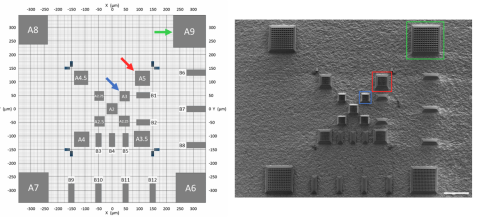
The layout of this phantom comprises 13 separate square arrays of interconnected square micromirrors with interstitial steeply sloped walls (Figure 1). Each array has uniform center-to-center (c-c) micromirror spacing along the two orthogonal axes. The arrays cover a 2-9 µm c-c spacing range, which approximates the retinal cone mosaic from the fovea to 6° eccentricity. The arrays are distributed on a flat surface over a 700 × 700 µm² area, which corresponds approximately to a 3° × 3° retinal field of view (FOV), with micromirror spacing and overall array size increasing from the center outward. Compressing the range of c-c spacings to a smaller FOV than an actual retina accommodates the typical 1-4° FOV of single AO image acquisitions, creating the opportunity for rapid phantom usage. To facilitate image orientation and scaling, high-contrast bars are strategically placed between the arrays. Only a narrow region at the center of each bar provides a flat surface for high-contrast AO visibility.
The arrays and bars are 3D-printed onto a 1” diameter BK7 ground glass diffuser (DG10-1500, Thorlabs, Newton, NJ), which possesses a highly randomized fine surface texture. This surface provides diffuse reflection of the AO beacon beam, filling the imaging system pupil uniformly for optimum AO wavefront sensing. Refractive index matching between the print material and the glass limits visibility of the random texture through the printed structures. To visually delineate the arrays and bars clearly from the random texture in acquired images, each array and bar is bounded by sloped walls to create a perimeter of low effective reflectivity similar to what surrounds each individual micromirror.
The phantom is installed in a model eye constructed with (1) a 12.5 mm diameter, 17.5 mm focal length achromatic doublet lens with anti-reflective coating (49-952-INK, Edmund Optics) to model all the refraction of an emmetropic human eye (60 diopters total), and (2) an opto-mechanical mount which permits x-y translation of optical elements at one end (CXY1A, Thorlabs). With the lens attached to the fixed end of this mount and the phantom attached to the translating end, any of the phantom’s arrays and bars can be precisely centered within the imager FOV without moving the eye. The phantom surface is axially positioned at the lens focal plane within the model eye mount. The polished back surface of the diffuser is lightly scratched to eliminate specular reflections of the AO imaging beam at this glass-air interface.
Intended Purpose
The phantom is intended to be used to assist the characterization of resolution and contrast for AO imaging system performance.
Testing
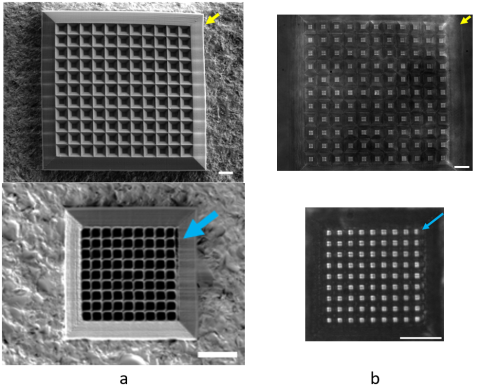
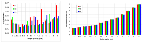
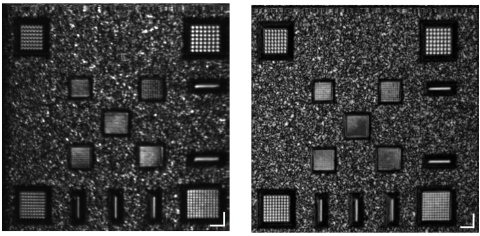
We have performed high magnification inspection and metrology independent from AO imaging on three fabricated phantoms. Figure 2a shows scanning electron microscopy (SEM) images which document defects in individual arrays. Figure 2b shows reflected light microscopy (RLM) images of the same arrays as in Figure 2a, with the same defects visible. Micromirror brightness variability and true c-c spacing were measured from the RLM images (Figure 3). True spacing measurements were enabled by spatially calibrating the RLM camera with high precision test targets. Figure 4 shows AO images from two different modalities, SLO (Figure 4a) and OCT (Figure 4b).
Limitations
Though the phantom has 3D features, the images it yields have primarily 2D information, from the micromirror and bar surfaces. 3D imaging modalities like AO-OCT can visualize some of the 3D structure, but the vertical extent of structures is on the order of OCT axial resolution and therefore difficult to quantify. The phantom acts like a surface reflector unlike biological tissue, which produces volumetric scattering.
The model eye in which the phantom is imaged approximates normal human refraction but otherwise does not replicate optical properties of the human eye. The axial length is much shorter than a human eye, which can pose challenges during AO-OCT imaging in locating the phantom surface within the coherence gate. Because the model eye is filled with air instead of aqueous media, the refractive index differential between air and the phantom’s materials is large and generates high intensity reflections which may exceed AO imaging sensor limits.
Supporting Documentation
Peer-reviewed journal article describing the AO phantom:
A. Agrawal, I. Rosenthal, D. M. Fitzgerald, Z. Liu, D. X. Hammer, R. D. Sochol, and A. Agrawal, “3D-printed phantoms for measuring lateral resolution and contrast performance of ophthalmic adaptive optics imaging systems,” Biomedical Optics Express, accepted for publication (2025). DOI: 10.1364/BOE.551755
Contact
Tool Reference
- RST Reference Number: RST26OM04.01
- Date of Publication: 05/05/2026
- Recommended Citation: U.S. Food and Drug Administration. (2026). Phantom for Measuring Lateral Resolution and Contrast of Ophthalmic Adaptive Optics (AO) Imaging Systems (RST26OM04.01). https://cdrh-rst.fda.gov/phantom-measuring-lateral-resolution-and-contrast-ophthalmic-adaptive-optics-ao-imaging-systems