
Catalog of Regulatory Science Tools to Help Assess New Medical Devices
This regulatory science tool (RST) is a method for assessing the image quality of a head mounted display using the display’s transverse chromatic aberration characteristics to align the light measuring device to the eye-point/ center of the eye-box.
Technical Description
Accurate measurements of image quality on head mounted displays requires alignment of the Light Measuring Device (LMD) to the Head Mounted Display (HMD). TCA are due to the refractive index of the HMD optics varying with wavelength, which results in a wavelength dependent magnification. TCA are minimized along the optical axis of the HMD and can be used to determine the center of the eye-box. This measurement has been applied to virtual reality HMD that exhibit measurable TCA, such as wide field of view HMD using Fresnel lenses. The method is intended to find the x,y eye-point location within the eye-box. The details are described in a peer-reviewed publication [1] and Section 19.3.5 of Information Display Measurements Standard, SID, 2023.
Test Pattern: TCA is measured using a pattern consisting of narrow red, green, and blue bars, such as one HMD pixel wide (or the minimum feature size through the rendering pipeline) displaced vertically by the height of the bar along the horizontal with a spacing of a few degrees in the field of view. The same pattern is used for the vertical direction, where the bars are displaced by the width of the bars in the horizontal direction (Fig. 1).
Image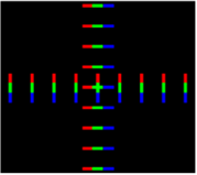
Figure 1. Example test pattern for eye-box centering using chromatic aberrations.
- Experimental setup: This method uses a high-resolution color or monochromatic array LMD mounted on a 3-axis stage to align the center of the entrance pupil of the Near Eye Display. Technical requirements on the LMD used are specified in IEC 63145-20-10 standard [3] and Sec. 19.2 of the Information Display Measurements Standard (IDMS) [4].
- Image acquisition and processing procedures: The TCA of the HMD is calculated from the location of the center of the red, green, and blue bars on the camera. This can be accomplished by taking the horizontal and vertical profiles for each colored bar across the image. To improve the signal-to-noise and average over the subpixel pattern, it is recommended to sum HMD 25 pixels in the direction perpendicular to the measurement direction. In other words, sum HMD 25 pixels in the vertical direction when determining the horizontal TCA for each colored bar. The camera should have sufficient resolution to resolve the bars as well as subpixel pattern in the HMD to measure shifts in the bars by one HMD sub-pixel. After acquiring an image, the location of the minimum TCA in the image is determined, which is the eye-point of the eye-box.
Intended Purpose
The purpose of this RST, an alignment method, is to help position the LMD at the eye-point of the VR HMD, which is a necessary initial step prior to performing image quality measurements. The method can be implemented by both medical device developers and testing labs for bench testing for evaluation of the image quality on MXR devices.
Testing
The method has been extensively tested and verified on four VR HMDs: HTC VIVE, Oculus Rift, Oculus Go, and Samsung Gear. The test method involved repeated measurements of the TCA and alignment. The method was compared to alignment using maximum luminance. The test procedure and results are presented in Sec. 19.3.5 of Information Display Measurements Standard (IDMS) and in the following publications:
Beams, R., Kim, A. S., & Badano, A. (2019). Transverse chromatic aberration in virtual reality head-mounted displays. Optics express, 27(18), 24877–24884. https://doi.org/10.1364/OE.27.024877
Beams, R. & Kim, A.S., & Badano, A. (2020). Eye-box centering using chromatic aberrations of virtual reality head-mounted displays. Optical Architectures for Displays and Sensing in Augmented, Virtual, and Mixed Reality (AR, VR, MR). Vol. 11310. International Society for Optics and Photonics. https://doi.org/10.1117/12.2543257
Limitations
Alignment using TCA requires using a high-resolution array LMD, such as a color camera, and a 3-axis translation setup for positing the LMD. This RST requires the rotationally symmetric optical elements in the HMD that exhibit TCA, which is generally the case for VR HMDs.
Supporting Documentation
Beams, R., Kim, A. S., & Badano, A. (2019). Transverse chromatic aberration in virtual reality head-mounted displays. Optics express, 27(18), 24877–24884. https://doi.org/10.1364/OE.27.024877 Beams, R. & Kim, A.S., & Badano, A. (2020). Eye-box centering using chromatic aberrations of virtual reality head-mounted displays. Optical Architectures for Displays and Sensing in Augmented, Virtual, and Mixed Reality (AR, VR, MR). Vol. 11310. International Society for Optics and Photonics. https://doi.org/10.1117/12.2543257 Reference standard documents:
Section 19.3.5 in Information Display Measurements Standard, SID, 2023 IEC 63145-20-10:2019 Eyewear display - Part 20-10: Fundamental measurement methods - Optical properties IEC 63145-20-20:2019 Eyewear display - Part 20-20: Fundamental measurement methods - Image quality.
Contact
Tool Reference
- RST Reference Number: RST24MX05.1
- Date of Publication: 06/20/2024
- Recommended Citation: U.S. Food and Drug Administration. (2024). Head Mounted Display Eye-box Centering using Transverse Chromatic Aberrations (RST24MX05.1). https://cdrh-rst.fda.gov/head-mounted-display-eye-box-centering-using-transverse-chromatic-aberrations-0