
Catalog of Regulatory Science Tools to Help Assess New Medical Devices
This regulatory science tool (RST) is a laboratory method for measuring the geometric distortion of the physical space observed with video see-through (VST) head-mounted displays (HMDs).
Technical Description
This regulatory science tool (RST) is a method for measuring the geometric distortion of the physical space observed with video see-through (VST) augmented reality (AR) head-mounted displays (HMDs). The method describes a monocular approach using a goniometric bench setup.
VST AR HMDs reconstruct the physical world using outward-facing RGB or monochromatic cameras and depth sensors. One of the major challenges for VST HMDs is the geometric distortion of the physical pass-through content, which is primarily due to the misalignment between camera and human eye positions. Although software-based distortion correction techniques may partially mitigate the lens distortion of the camera and eyepiece lenses, it is challenging to address VST geometric distortion without introducing occlusion errors. As spatial accuracy is critical for many applications of medical extended reality (MXR), geometric distortion of the VST physical content needs to be evaluated.
This RST describes considerations for the physical target design, experimental setup, VST geometric distortion measurement and processing procedures as follows [1]:
- Physical target: A 2D dot array (e.g., 9 x 9 dot array following the ISO 9241-392:2015 standard [2]) with dot diameter of 2 to 5 mm and known spacing that covering an area of at least 30 x 30 cm2. This can be a physical target with adequate contrast between the dots and surrounding background or digital pattern rendered on a large area flat-panel display [1].
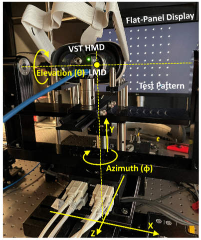
- Experimental setup: This method uses a high-resolution camera as the light measuring device (LMD). As illustrated in the figure below, the evaluated VST HMD and LMD are mounted on a set of linear translation and rotation stages that enabled linear translation in three degrees of freedom (DoFs) and goniometric rotation of the LMD in two DoFs (azimuth φ, and elevation θ). The LMD rotation center is positioned at the corresponding eye rotation center. This goniometric setup emulates the eye rotation geometry with detailed technical requirements described in the IEC 63145-20-10 standard [3] and Information Display Measurements Standard (IDMS) [4]. Alternatively, the LMD may be mounted on a robotic system. The optical axis of the LMD needs to be perpendicular to the 2D dot array target and aligned to the central dot. Prior to geometric distortion measurements, the distance from the physical target and the LMD rotation center should be precisely measured or calibrated. After fixing the placement of the LMD, the eye point of the evaluated VST HMD need to be aligned with the LMD.
- VST geometric distortion measurement and processing procedures: Detailed procedures for implementing the VST geometric distortion method are described in [1] and the Instructions manual [5]. For each dot on the physical target with known physical location, the azimuth and elevation angles (φ, θ) of the LMD are determined by the goniometer when the optical axis of the LMD aligns with the dot shown on the VST AR HMD (i.e., the virtual representation of the physical dot passing through the HMD). The corresponding back-projected 3D locations of the virtual dot can be determined and the distance (d) between the back-projected dot position with respect to the physical position can be determined. After repeating the above procedures for all the dots, a distortion map of spatial error can be generated as the output of the measurement.
Detailed step-by-step instructions on implementing this tool are described in [5].
Intended Purpose
This method is intended to characterize the geometric distortion of the physical space observed with VST HMDs using a monocular goniometric bench setup.
The method is primarily developed for video see-through AR HMDs, but it is also applicable to optical see-through AR HMDs if physical geometric distortion is a concern. The method can be implemented by medical device developers and testing houses for evaluating the MXR devices.
Testing
The method has been extensively tested and validated on two HMDs: Meta Quest 3 and HTC VIVE XR Elite HMDs. The Meta Quest 3 has dual-camera design, while the HTC VIVE XR Elite uses a single camera. The method is generalizable for VST HMDs with various hardware design and software platforms.
Limitations
The method described in this RST can measure VST geometric distortion at a single distance where the 2D target is located. This method does not include depth estimation using a monocular bench setup. Distortion correction algorithms may partially mitigate the VST distortion at a single distance but could be challenging for multi-distance 3D correction.
Supporting Documentation
The method with detailed instructions and validation are described in the following publication:
[1] Zhao, C. and Beams, R., 2024. Geometric distortion on video see‐through head‐mounted displays. Journal of the Society for Information Display, 32(5), pp.184-193.
Reference standard documents:
[2] ISO 9241-392:2015, “Photography – Digital cameras – Geometric distortion (GD) measurements,” International Organization for Standardization (2015).
[3] IEC 63145-20-10:2019 Eyewear display - Part 20-10: Fundamental measurement methods - Optical properties.
[4] Information Display Measurements Standard, SID, 2023.
Instructions manual:
Contact
Tool Reference
- RST Reference Number: RST26MX02.01
- Date of Publication: 05/04/2026
- Recommended Citation: U.S. Food and Drug Administration. (2026). Geometric Distortion Measurement Method on Video See-Through Augmented Reality Head-Mounted Displays (RST26MX02.01). https://cdrh-rst.fda.gov/geometric-distortion-measurement-method-video-see-through-augmented-reality-head-mounted-displays